Download the current
TC-64 manual here.  (Rev-5 30 October, '08)
Download the latest
TC-64 DecoderPro file here. (Version
03 October, '10)
This update to the previous October '08 file includes the correction of some long standing typos in the secondary message address section.
The latest additions to the JMRI Decoder file include configuration support for the new 'Dual Coil' mode available with Rev-5 firmware.
This DecoderPro file includes the "Factory Reset" option, and corrected "Reset To defaults" settings. A TC-64 that has been "Factory Reset" will have all of its settings erased and its OPS mode address set to 10000. Be sure you have saved any required data to a roster file before doing this. Factory reset may only be done in Service Mode. After a factory reset you must restore the desired OPs address to the unit, using service mode if more than one CV must be changed. Use the CV tab and individually write CV17 and CV18 as required. Once the proper OPs address has been restored, exit service mode and reprogram the rest of your required settings as normal in OPs mode.
Download the latest TC-64 firmware update here. (Rev-6F September '10)
All user settings remain unaffected by these firmware upgrades. However changes in Rev-5 firmware will change the timing of intervals less than 1 second. Also blink rates are now twice the pulse rate, i.e. half of their previous rates. Units shipped after the effective date will contain the version of firmware current at the ship date. Read SV21 with DecoderPro to determine the firmware version number of your unit. Updates are cumulative. You only need to install the most current version. Multiple units may be upgraded at one time.
To install a firmware upgrade using DecoderPro version 1.7.5 or later choose "Download Firmware" under the LocoNet tab. WARNING! Do NOT use JMRI versions 2.2 thru 2.3.2 to upgrade TC-64 or LocoBuffer-USB firmware! A bug was introduced during an upgrade to the 'Download Firmware' code of JMRI 2.2 that will disable your unit. JMRI 2.0 or earlier works OK, and the bug was repaired in JMRI version 2.3.3. Select file format '16 bit' when loading updates to a TC-64 or a LocoBuffer-USB using version 2.3.3 or later. To recover a disabled unit, upload the correct version of JMRI and then follow the proceedure described below for an interrupted download.
When the Firmware Downloader window opens, first select file format '16 bit' then 'Select' the file you want to download, then click on "Read file" to load it into DecoderPro. Next, using a bent paper clip, press and hold the "Program" switch on the TC-64 for 10 seconds until the command light comes on steadily. Now click the "Download" button in the Firmware Downloader window. The LocoNet activity light will show high activity for approximately 60 seconds while the firmware is upgraded. Normal operation of the TC-64 should resume automatically at the end of the upgrade process.
Do not interrupt this process or you will end up with currupted firmware. To recover from a corrupted upgrade you must unplug the power to the TC-64, then, while holding the program switch depressed, plug in the power again. This will place the unit directly into program mode and allow you to resend the upgrade file. The boot loader code itself is protected against being written over.
TC-64 Revision History:
Rev-6F (tc64ln_V6F_Update_keep_Config.hex) This revision corrects some bugs in the output status initial reporting. The TC-64 will now correctly report its (automatically restored) output states during initialization. The code now has a random response backoff time to reduce the number of collisions when multiple units are first initialized simultaniously. An option has been added in the JMRI configuration file to enable output state readback during initialization.
Rev-6F-full (tc64ln_V6F_Update_with_Config.hex) Warning, this file restores all the code, including the CV settings stored in EEPROM, to the factory default values! This includes the TC-64 unit address which will revert to 10000. All user configuration settings will be lost. Be sure to save your configuration information to a roster file prior to uploading this file. After installing this file you will need to reset the unit address using 'Service Mode' prior to re-loading your user settings using 'OPS Mode'.
Rev-5K (tc64ln87_11_4_5K_5_update_keep_config.hex) This revision corrects additional bugs in the secondary message code related to Switch Feedback and General Sensor secondary messages.
Rev-5K-full (tc64ln87_11_4_5K_5_update.hex) Warning, this file restores all the code, including the CV settings stored in EEPROM, to the factory default values! This includes the TC-64 unit address which will revert to 10000. All user configuration settings will be lost. Be sure to save your configuration information to a roster file prior to uploading this file. After installing this file you will need to reset the unit address using 'Service Mode' prior to re-loading your user settings using 'OPS Mode'.
Rev-5 (tc64ln87_11_4_5_5_update_keep_config.hex) This revision corrects several bugs in the secondary message code. It also adds the new 'Dual-Coil' option for driving solenoid powered switch machines and other dual coil devices. The definition of blink timing has changed, so you may need to reset any blink timings. Pulse time is now 1/2 of blink time. I.e. one full blink cycle is now equal to twice the pulse time.
Rev-5-full (tc64ln87_11_4_5_5_update.hex) Warning, this file restores all the code, including the CV settings stored in EEPROM, to the factory default values! This includes the TC-64 unit address which will revert to 10000. All user configuration settings will be lost. Be sure to save your configuration information to a roster file prior to uploading this file. After installing this file you will need to reset the unit address using 'Service Mode' prior to re-loading your user settings using 'OPS Mode'.
Rev-4 (tc64ln87_11_4_4_5_update_keep_config.hex 4-27-08) This revision corrects a bug in the collision detection that could cause an occasional data loss during high LocoNet traffic. This is especially noticable when used with RR&Co software for automatic train control.
Rev-4-full (tc64ln87_11_4_4_5_update.hex 4-27-08) Warning, this file restores all the code including the CV settings stored in EEPROM to the factory default values! This includes the TC-64 unit address which will revert to 10000. All user configuration settings will be lost. Be sure to save your configuration information to a roster file prior to uploading this file. After installing this file you will need to reset the unit address in Service Mode prior to re-loading your user settings.
Rev-3 (tc64ln87_11_4_3_5_update_no_config.hex 9-23-06) This revision corrects a bug in the pin handling of the sensor outputs when an output was in "Respond to Sensor Feedback" mode. The 8 output lines did not properly track the sensor message values.
Rev-3-full (tc64ln87_11_4_3_5_update.hex 9-23-06) This file restores all the code including the CV settings stored in EEPROM to the factory default values. This includes the TC-64 unit address which will revert to 10000. All user configuration settings will be lost. Be sure to save your configuration information to a roster file prior to uploading this file. After installing this file you will need to reset the unit address in Service Mode prior to re-loading your user settings.
Rev-2 (tc64ln87_11_4_2_5_update_no_config.hex 9-12-06) This revision changes the original signal mode definition that caused signal mode and two turnout mode to behave differently. This upgrade changes the behavior of signals controlled in the Digitrax SE8c compatible mode. (signal mode)
Rev-2-full (tc64ln87_11_4_2_5_update.hex 9-12-06) This file restores all the code including the CV settings stored in EEPROM to the factory default values. This includes the TC-64 unit address which will revert to 10000. All user configuration settings will be lost. Be sure to save your configuration information to a roster file prior to uploading this file. After installing this file you will need to reset the unit address in Service Mode prior to re-loading your user settings.
To upgrade the TC-64 DecoderPro file reflecting these changes. Download this decoder file (RR-CirKits-TC-64-basic.xml) and use it to replace the one found in the "\JMRI\xml\decoders" folder from 1.7.5 or earlier. (Updated 14 Oct, '06)
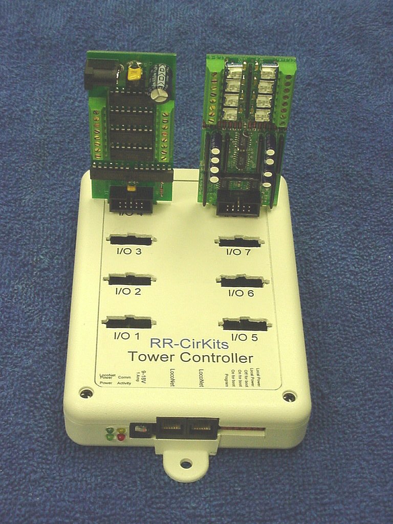
Prototype of the new RR-CirKits 64 line Tower Controller.
(Prototype units pictured) Shown with
Octal "H" bridge driver and original version of the 8 block CT (current
transformer) occupancy detector daughter cards. Daughter cards may be
plugged directly into the Tower Controller or for those with limited
space or difficult mounting situations, they may also be mounted
remotely and connected to the Tower Controller with a standard 10 pin
flat cable.
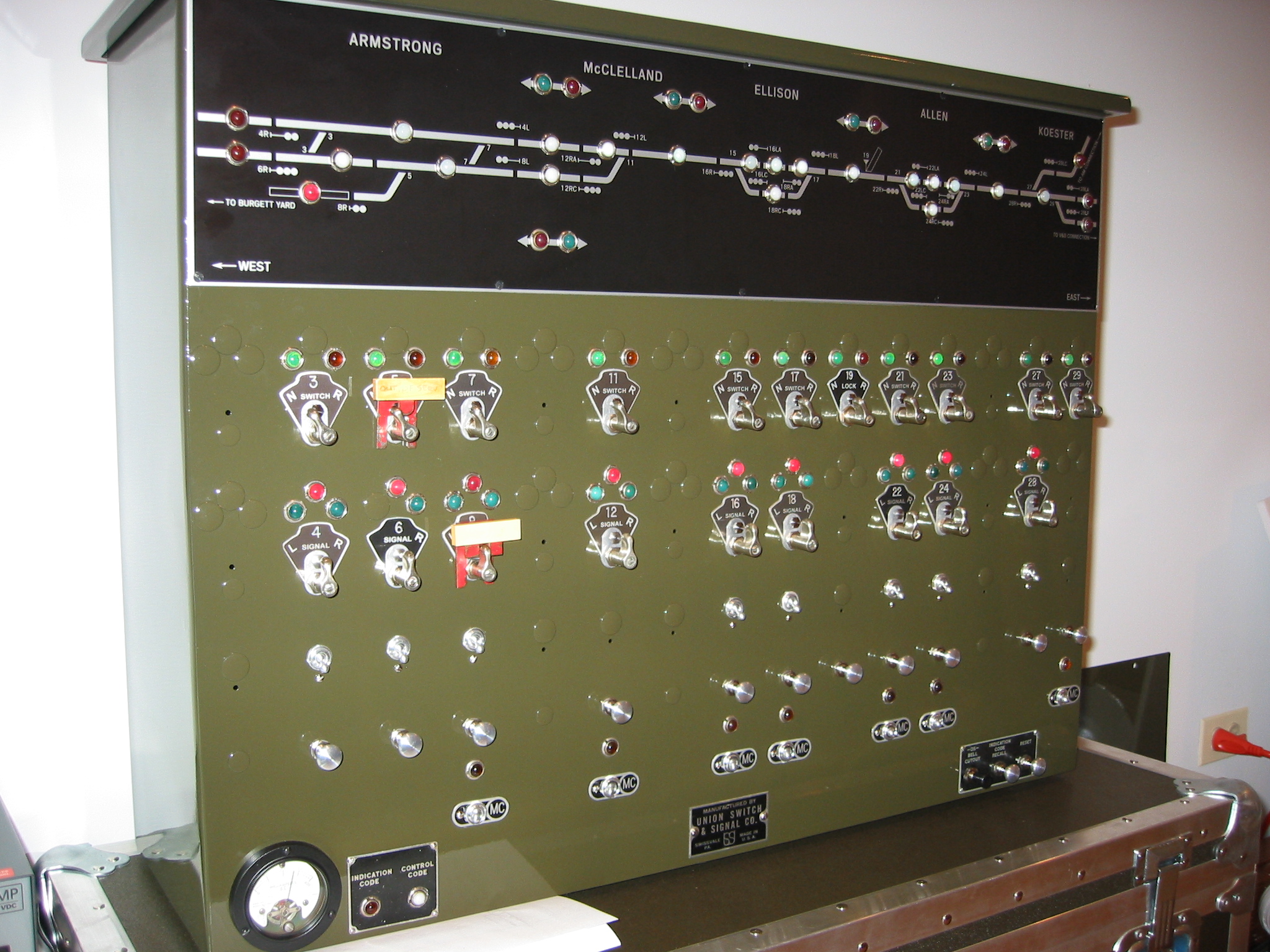
Front view of Mike's panel. Click on image
to enlarge detail.
.
Click here for
more images of this panel. (high speed
internet access advised)
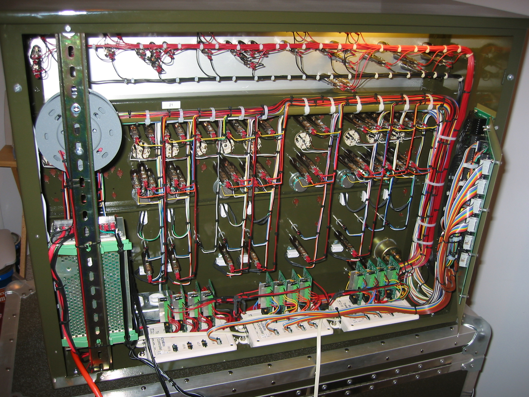
This installation uses 12 "H" bridge drivers in single ended mode to drive the ninety two 24 volt lamps, meter, and bell. All switch and lever inputs simply connect to ports configured to be Tower Controller inputs. Mike chose the "H" bridge driver boards for their relatively high voltage and current drive capability. The large board to the right was created by Mike as a termination point for his harness and conversion to the ribbon cables connecting to the Tower Controller inputs. (click on image for a larger version)
The RR-CirKits Tower Controller is designed to make multiple functions of your choice available at each major junction, passing siding, or control panel on your layout. This can reduce the wiring complexity and cost of adding signals, occupancy detection, turnout control, push buttons, LED's, and many other animation functions associated with each location on your layout. Each of the 8 ports supports 8 lines of input or output data, plus the 5V power required by most of the various daughter cards. Dual coil and DC turnout driver ("H" bridge) daughter cards will require separate isolated power supplies. (or common ground with the Tower Controller)
Updated CV info. New options for 64 line Rev-d board.
Some planning sheets to help setup the TC. Initial setup. Basic Info.
Current status: First hardware shipping.
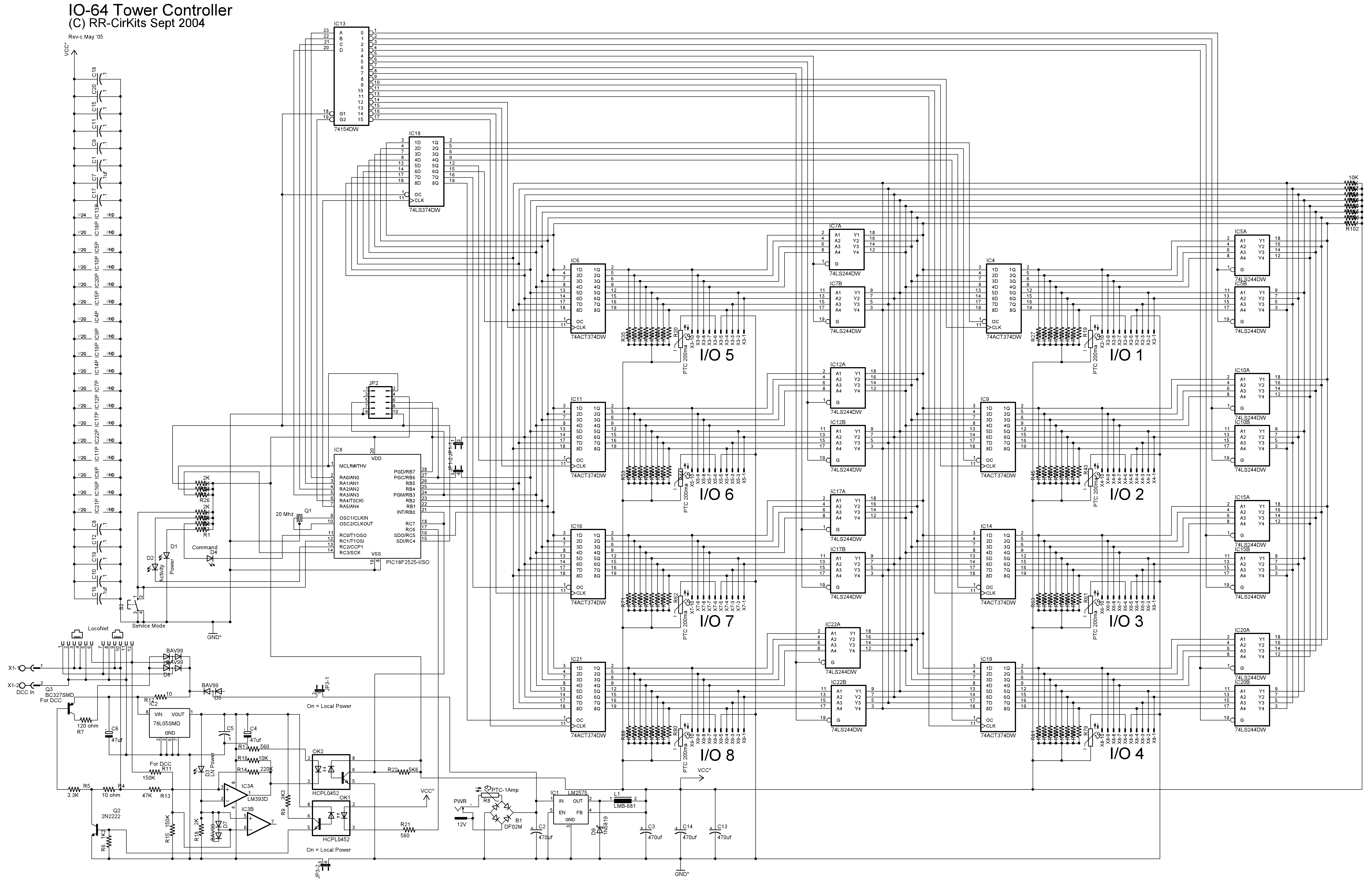
Tower Controller Board Rev-d
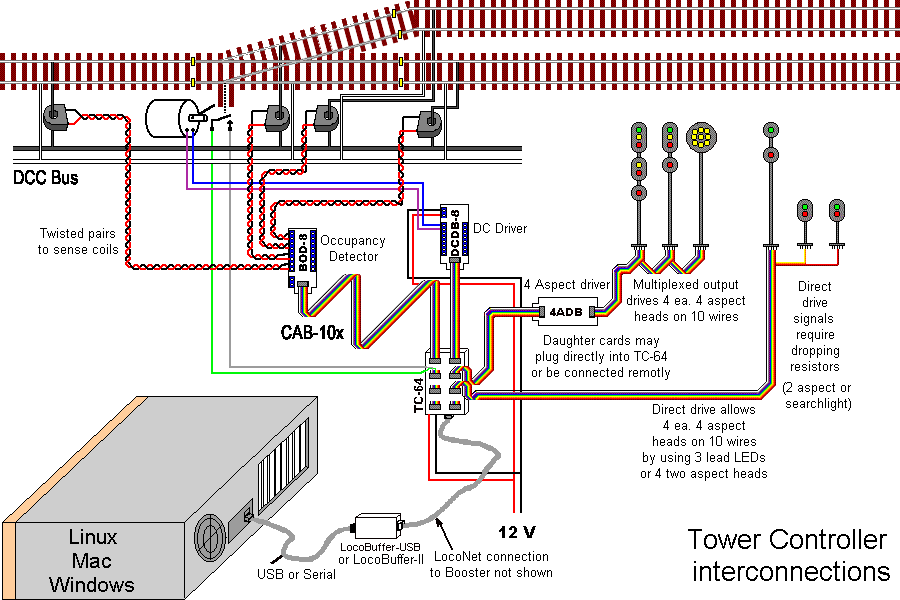
Tower Controller wiring diagram (Dec 6 '05) 64 line Rev-d Schematic (updated 22 Apr '06) Manual with SV values (updated 30 Oct '08)
This new board is designed to be compatible with the LocoNet control bus (but not yet LocoNet certified) and includes the following features.
Uses a PIC18F2525 running at 20Mhz for ample stored SV capacity. One controller for multiple functions allows a low cost per line. Replaces 8255 boards in many RR-CirKits applications. LocoNet (not yet certified) inputs are opto isolated to prevent power supply ground loop problems. On board termination for all I/O pins. (4.7K pull ups) 64 lines of Input/Output. Direction is an SV controlled option in 8 line groups. Each 8 line group is connected to it's own 10 pin RR-CirKits standard connector. Input from BOD, switch contacts, etc. Drive DDB, LED's, etc. Cool running internal 1 Amp switching power supply (8 - 35 VDC or 6 - 24 VAC input) powers the controller plus most daughter cards. Serial port Boot Loader Programming option for experimenters and upgrades. Individually buffered outputs allow for full 15 ma. load on all output lines simultaneously. Each 8 line port has it's own SV stored starting address. Master reset option for all SV's except port addresses. Option to store all output states during power down. (Prevents switch machines and signals from throwing randomly on power up.) Optional Ops Mode programming. Paged mode programming without connecting to the programming track. DecoderPro support planned. Each line has it's own SV programmable input or output features. Input: Transition state and polarity. Output: Steady, Pulse, Blink, and Invert of all. Each input or output line transition may optionally output a secondary (cascade or slave) command to any DCC address. (two SV's per line, command + address) This option allows for many interesting options such as single button ladder routing and master/slave control panels. Linux, PC and Mac software available from JMRI to calculate SV values and send programming commands. Read back of SV values in Ops Mode or Service Mode.